Zero-offset ray tracing in the smoothed Marmousi model
This is an example of the zero-offset ray tracing.
The calculation is performed in the smoothed Marmousi model
obtained by running the history file 'mar-inv.h', see the description
mar-inv.htm.
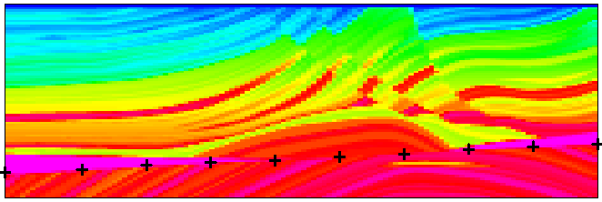
The initial surface (exploding reflector) corresponds to the velocity
discontinuity in the lower part of the original "hard" Marmousi model.
The points at the initial surface
have been found using the program
grdiso.for:

Figure 1: Velocity in the original "hard" Marmousi model.
The points identified at the velocity discontinuity in the lower part
of the model are indicated by black crosses.
The initial surface is then interpolated by B-splines, see the data file
RPAR.
The receivers are located
at the Earth's
surface, the distance between the receivers is 80 m. The two-point
ray tracing from the initial surface to the receivers is managed by
history file mar-crtz.h.
The history file
generates also a plot of the calculated zero-offset two-point rays.

Figure 2: Velocity in the smoothed Marmousi model.
The calculated zero-offset two-point rays
are plotted by black lines.
A picture of two-point rays together with the
auxiliary rays may be also generated.

Figure 3: Velocity in the smoothed Marmousi model.
The calculated zero-offset two-point rays
are plotted by black lines,
the auxiliary rays traced during the zero-offset two-point ray tracing
are plotted by white lines.
Click on the picture for larger view.


